EXPERTISE
Structural Engineering
Reliability and Transparency in Maritime Engineering
Structural Design & Arrangement
We carry out structural design and arrangement of various members to achieve the required strength along with optimizing the weight. Various longitudinal and transverse bulkheads are arranged to create the required compartmentation in addition to being primary supports. Primary members – long girders and other web frames are arranged to meet the longitudinal and transverse strength requirements.
Rule Scantlings
Scantlings based on classification society’s rules are developed and analyzed for meeting various strength requirements.
Finite Element Analysis
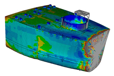
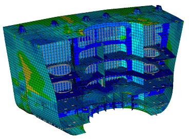
Different type of finite element analysis are performed to check the structural stability and integrity of any structure namely: yield strength check, buckling and ultimate strength check, fatigue analysis, dynamic analysis, joint strength analysis and hydrostatic and soil collapse analysis etc. Every finite element analysis can be split into two main parts i.e. pre – processing and post – processing.
Pre – Processing
A. Structural modeling:-
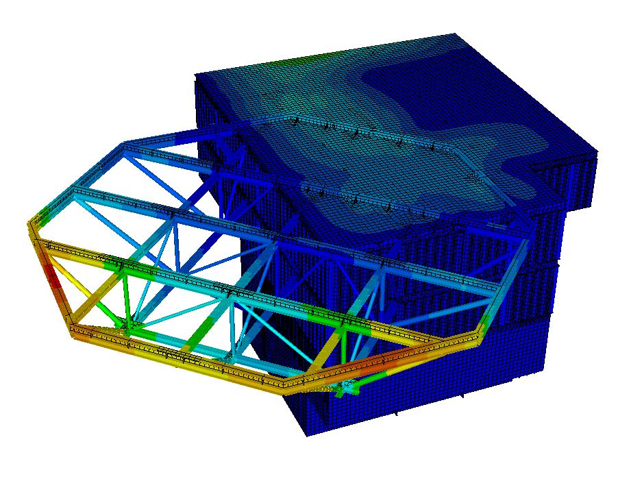
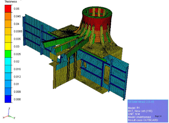
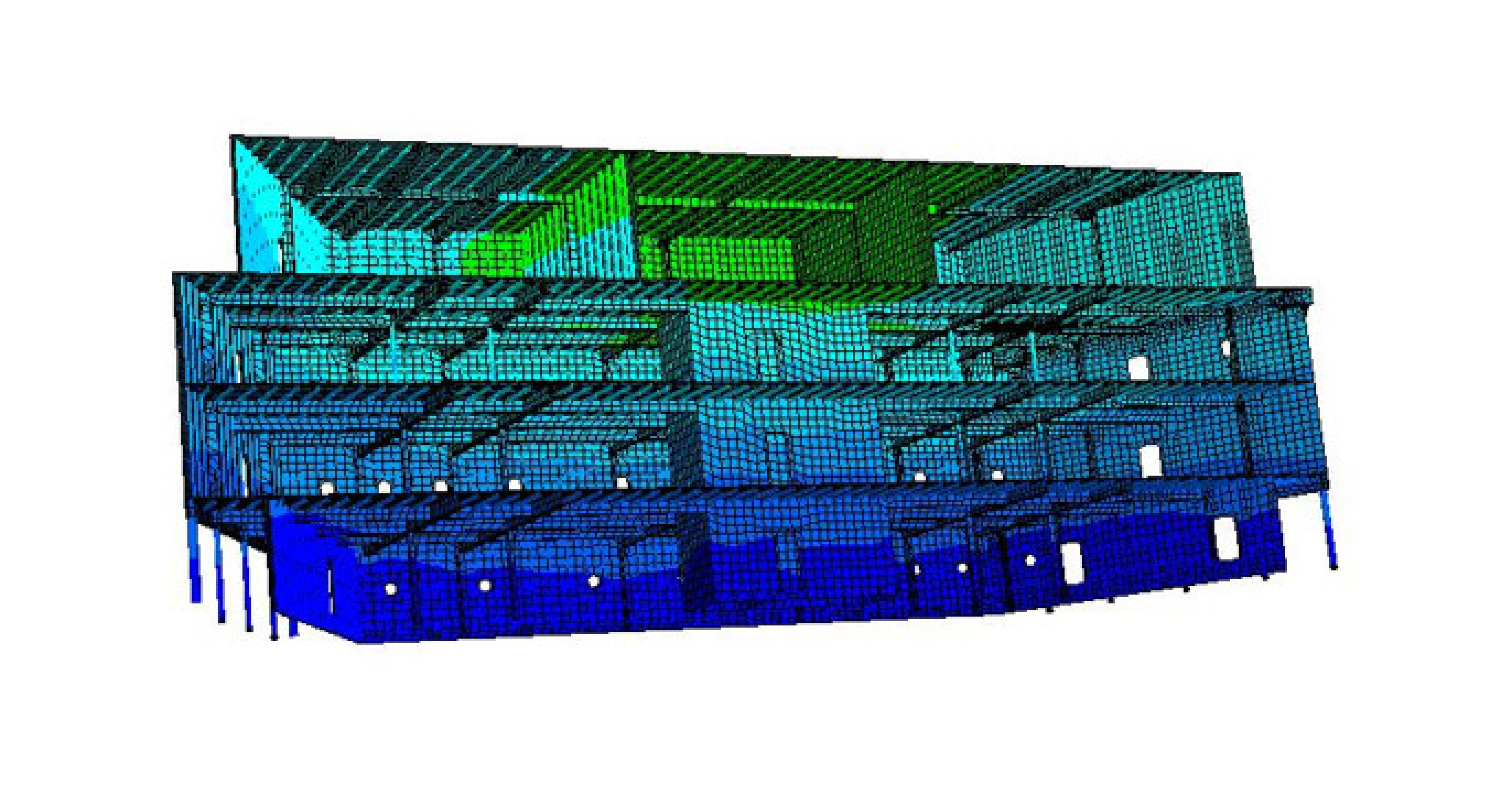
In this aspect of pre – processing, extent of the structural modeling required for the analysis is decided. Structural model is generated as a combination of space frames (beam elements) and 2D finite elements. Surface modeling for deck, bottom, shell, bulkhead plating and girders is carried by 2D finite elements and stiffeners, truss structures are modeled as space frames (beam elements).
For any local analysis structure model can be generated from the global structural model if available and similarly for global analysis model can be generated by combining all local models available.
B. Proper idealization of structural behavior:-
Proper idealization of structural behavior is the core expertise of the structural engineer and analysis becomes very accurate with proper idealization. Hence extreme care is taken to idealise the structure and reviewed.
C. Discretisation of the model (Meshing):-
Discretisation is an important aspect of any finite element analysis. Quality of discretisation has a major impact on quality of results and the computational time of the analysis. Quadrilateral structured mesh is always preferred for any type of finite element analysis but in case of very complex geometry tetrahedral mesh can be used when aspect ratio and Jacobian are within acceptable limits. Mesh size also influence the computational time and quality. For global yield and buckling analysis mesh size equal to stiffener spacing is widely used and for local analysis mesh size of around 0.1m is used in offshore industry. For fatigue analysis “t x t meshing” (i.e. size of the meshing for critical regions should be of thickness of adjacent plate) is used.
D. Boundary conditions:-
Boundary conditions are used to prescribe values of basic solution variables; for example, displacements and rotations in stress/displacement analysis. Selecting the proper boundary condition has an important role in structural analysis. Effective modeling of support conditions requires a careful consideration of continuity of each translational and rotational component of displacement. For a static analysis, it is common to use a simpler assumption of supports (i.e. fixed, pinned, roller) without considering the soil/ foundation system stiffness. However for dynamic analysis, representing the soil/foundation stiffness is essential.
E.Loading:-
Loads can be classified in mainly two categories i.e. dead load and live loads.
Dead loads are the loads of constant magnitude and remain in one position, it may include the self weight of the structure, tank loading and other loads such as piping and machinery loads that are permanently attached to the structure.
Live loads are the variable loads that may change in position and magnitude. Live loads include those caused by construction operations, wind, waves, current, earthquakes, snow, blasts, walkway loading, temperature changes and transit inertial loads (cause additional accelerations on the structure due to motion of the vessel during transit condition).
Post – processing
After completing the pre – processing and performing the analysis, post – processing is carried out
A. Graphical representation of induced stresses:-
After completing the analysis different components of the induced stresses are graphically represented. For yield strength check bending, shear and von mises stress components in all three directions are presented for the analysis. For buckling strength analysis bending, shear, twisting and von mises stresses decomposed in membrane in all the directions are graphically represented and for fatigue analysis principal stresses are graphically represented.
B. Graphical representation of induced displacements:-
Graphical representation of displacement of the structure is required for understanding the behavior of the structure.
C. Unity check calculations for space frames:-
Unity check calculations are required for the space frames or beam elements. Code check calculations are required mainly for boom rest, flare boom, helideck etc and similar type of structures. Code check are performed using various unity check codes like, AISC ASD, AISC LRFD, API LRFD, API WSD, ISO standards, Danish standards and NORSOK standards etc. depending on the class of the vessel.
D. Unity check calculations for joint check analysis:-
Along with the unity check for beams, unity check for tubular joints is also required. Unity check for tubular joints are done using various codes. Joint checks are performed for mainly truss type of structures like boom rest, flair boom and leg of jack up etc.
E. Calculation of reactions induced by applied loads:-
Reactions induced by the applied external loads are to be calculated and presented for further analysis such as eye pad analysis, reactions from topside structure for analysis of stool structure etc.
Buckling and Ultimate Strength Analysis
Buckling and ultimate strength is another very important aspect of structural design as all the shell plates, girders etc are subjected to highly compressive stress. Their buckling and ultimate strength assessment becomes the most important factor for design.
Buckling and ultimate strength evaluation is performed for following structural steel components or assemblages:
A. Individual structural members (i.e. discrete beams and columns).
B. Plates, stiffened panels and corrugated panels.
C. Stiffened cylindrical shells and Tubular joints.
As buckling and ultimate strength of structural components are highly dependent on the amplitude and shape of the imperfections, these are implicitly considered in the strength assessment analysis.
Buckling and ultimate strength analysis is performed for all the loading conditions considered in yield strength analysis. For buckling and ultimate strength check, membrane stresses are extracted from the finite element analysis results and the compressive stresses are screened. The critical panels of plating (deck, floors, stiffeners etc) are found by progressive screening for maximum membrane compressive stresses. The beam compressive stresses are also extracted from the finite element analysis results and the critical members are found out similarly as for plated panels.
- Structural Design & Arrangement
- Rule Scantlings
- Finite Element Analysis
- Buckling and Ultimate Strength Analysis


